BUILD GUIDE

Prepare. Watch. Assemble.

Print the parts you need and order the components. When you’re ready to build, take it one step at a time and follow the instructions.

Version V0.6 - R92
106–109Catalogue pieces, by options

Assembly steps

20 assembly cards. Quantities are for one rover unless a step explicitly says “per wheel”. Computer and camera options are alternatives.

Written guide
Identify every spacer and lock ring

SP01–SP12 and LK05/LK06/LK08: dimensions and matching STLs · Reference sheet · Spacer locations

01Choose the hull and fit the inserts
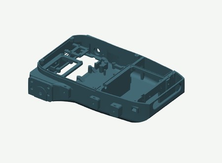
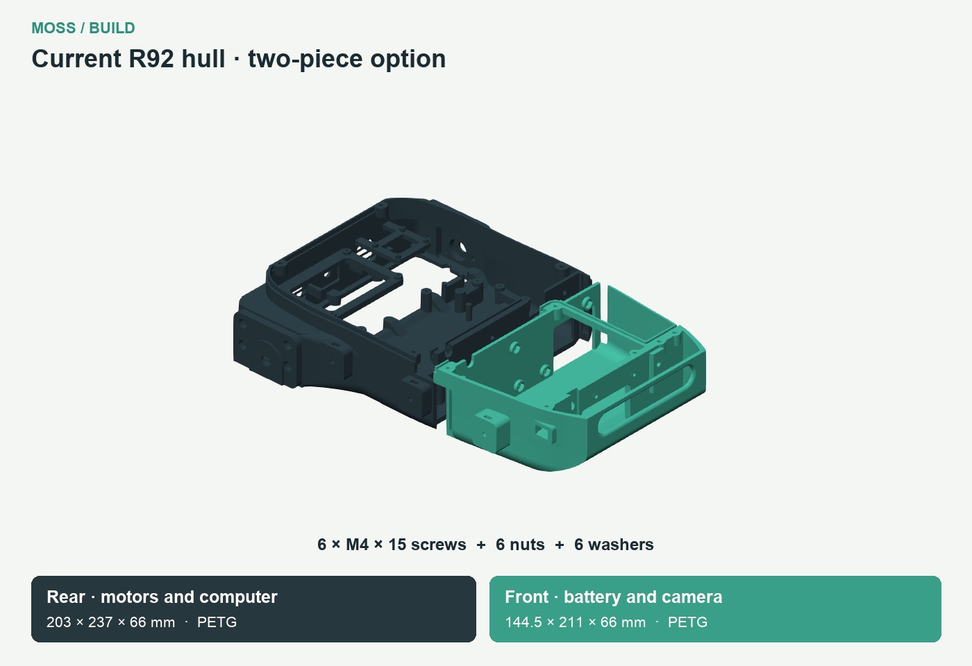
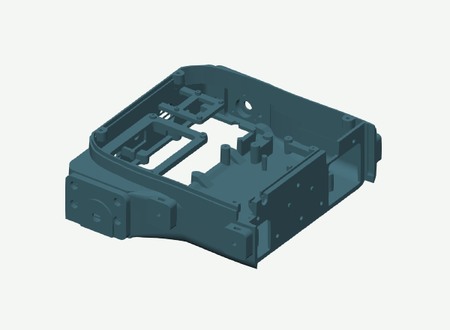
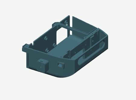
Current R92 split hull, motor/computer half and battery/camera half
PrepareQty
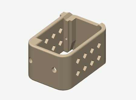
One-piece hull (one-piece option) · PETG1
Lidar Base · PETG1
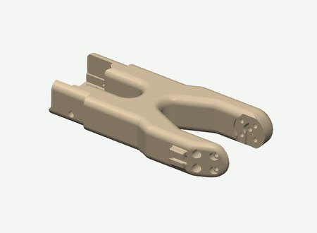
Rear hull — motors and computer · PETG1
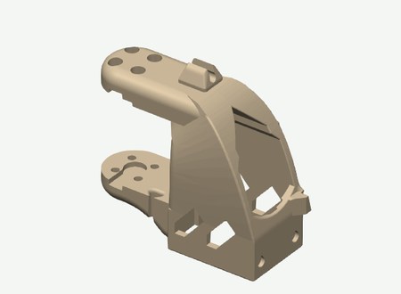
Front hull — battery and camera · PETG1
Epoxy from the two-part kit, for the hull jointAs needed
M3 heat-set insert, OD4 mm, length 6 mm11
Split hull only: M4 × 15 socket-head screw6
Split hull only: M4 hex nut, 7 mm across flats6
Split hull only: M4 washer, Ø9 × 0.8 mm6
  1. Choose the one-piece hull or both split halves. For the split hull, dry-fit both halves first, then apply a thin layer of two-part epoxy to the mating faces. Engage the locating pins, seat six nuts from the battery side, and fit six M4 × 15 screws with washers from the motor/computer side. Tighten progressively and let the epoxy cure before installing electronics or the battery.
  2. Use a soldering iron to fit the inserts: place each insert over its hole, heat it with the iron tip, then gently press it straight into the plastic. Fit four inserts for the cover, four for the arm plate and two for the LiDAR base in the hull.
  3. Use the same soldering-iron method to fit the remaining insert in the LiDAR base for the carriage lock. Keep the threads clear and let all inserts cool before fitting screws.
02Build the six road wheels

Fastening

PrepareQty
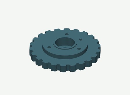
625 road wheel inner half (left + right) · PETG6
625 road wheel outer half (left + right) · PETG6
SP09 · Spacer road wheel center (left + right) · PETG6
625 bearing12
M3 × 35 socket-head screw18
M3 hex nut18
  1. For each wheel, prepare two printed halves, one SP09 centre spacer, two 625 bearings, three M3 × 35 screws and three M3 nuts.
  2. Insert each bearing through the open mating face of its wheel half. Do not push it through the smaller outside opening.
  3. Seat the three nuts in the inner half, position SP09 between the bearings, close the wheel halves, then insert the three screws from the outer face. Repeat six times.
03Build the two drive wheels
PrepareQty
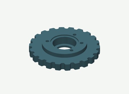
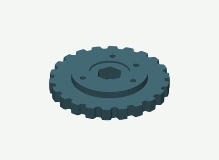
HEX12 drive wheel inner half (left + right) · PETG2
HEX12 drive wheel outer half (left + right) · PETG2
HEX12 metal hub, 6 mm bore, 18 mm length2
M3 × 20 socket-head screw6
M3 hex nut6
  1. Match the locating feature on each pair of halves.
  2. Close each wheel with three M3 × 20 screws and three M3 nuts. Keep the HEX12 seat clear.
04Build the two idler wheels
PrepareQty
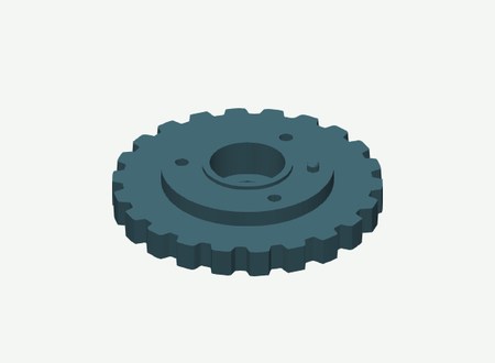
22T idler wheel inner half (left + right) · PETG2
22T idler wheel outer half (left + right) · PETG2
SP10 · Spacer tensioner center (left + right) · PETG2
608 bearing4
M3 × 25 socket-head screw6
M3 hex nut6
  1. For each idler, seat two 608 bearings with SP10 (centre spacer) between them.
  2. Close the two halves with three M3 × 25 screws and three M3 nuts. Repeat for the other side.
05Fit the motors and inner bearing retainers
PrepareQty
Motor Mount (left + right) · PETG2
bearing retainer (left + right) · PETG2
JGB37-520 motor, 12 V, 90:1, 110 rpm, Hall encoder2
626 bearing, inner2
Rigid coupling, 6 mm to6 mm2
M4 × 20 socket-head screw8
M4 hex nut8
M3 × 8 socket-head screw12
  1. Use three M3 × 8 screws per motor, without washers. The other six M3 × 8 screws secure the two bearing retainers.
  2. Put four M4 nuts into each motor-support nut pocket and secure each support to the hull with four M4 × 20 screws.
  3. Fit the inner bearing retainers with three M3 × 8 screws per side.
06Fit the inner track frames
PrepareQty
inner track frame (left + right) · PETG2
M4 × 15 socket-head screw6
M4 hex nut6
  1. Fit each inner frame directly against the hull.
  2. Use three M4 × 15 screws and three M4 nuts per side.
07Fit road-wheel axles and spacer pairs

Exploded assembly

PrepareQty
SP01 · Spacer road wheel inner ID01 (left + right) · PETG6
SP02 · Spacer road wheel outer ID02 (left + right) · PETG6
Smooth steel axle, 5 x70 mm finished length6
LK05 — shaft collar: 5 mm bore, 10 mm outside diameter, 5 mm long12
  1. Use SP01 (1 dot, 7.5 mm) on the inside and SP02 (2 dots, 5.5 mm) on the outside of every road wheel. SP09 (18 mm, no dots) sits between its bearings.
  2. Retain each axle with two LK05 collars (5 mm bore). Repeat for all six wheels and check free rotation.
08Fit the drive axles and outer bearing covers

Exploded assembly

PrepareQty
SP03 · Spacer drive inner ID03 (left + right) · PETG2
SP04 · Spacer drive outer HEX12 L12.6 ID04 (left + right) · PETG2
Cover motor bearing (left + right) · PETG2
SP11 · Drive bearing to collar spacer (left + right) · PETG2
Smooth steel axle, 6 x77 mm finished length2
626 bearing, outer2
LK06 — shaft collar: 6 mm bore, 11 mm outside diameter, 5 mm long2
M3 × 15 socket-head screw6
M3 hex nut6
  1. Use SP03 (3 dots, 7.6 mm) on the motor side and SP04 (4 dots, 12.6 mm) on the outer side of the drive wheel.
  2. Put SP11 (3.5 mm, no dots) between the outer 626 bearing and LK06 (6 mm bore). Secure each bearing cover with three M3 × 15 screws and nuts.
09Fit the idler slides and tensioners

Exploded assembly

PrepareQty
inner tensioner cover (left + right) · PETG2
SP05 · Spacer tensioner inner ID05 (left + right) · PETG2
SP06 · Spacer tensioner outer ID06 (left + right) · PETG2
Cover tensioner outer (left + right) · PETG2
Slider outer (left + right) · PETG2
inner tensioner slider (left + right) · PETG2
SP07 · Spacer tensioner retainer inner ID07 (left + right) · PETG2
SP08 · Spacer tensioner retainer outer ID08 (left + right) · PETG2
Smooth steel axle, 8 x87 mm finished length2
LK08 — shaft collar: 8 mm bore, 16 mm outside diameter, 8 mm long4
M3 × 15 socket-head screw16
M3 hex nut16
M4 × 35 socket-head screw4
M4 hex nut8
M4 washer4
  1. Inside to outside: LK08, SP07, inner slider, SP05, idler wheel with SP10 between its bearings, SP06, outer slider, SP08, LK08. Use two LK08 collars (8 mm bore) per axle.
  2. Fit each tensioner cover with four M3 × 15 screws and nuts. Use an M4 × 35 adjuster with its washer and two nuts at each of the four tensioners.
10Close the track frames

Exploded assembly

PrepareQty
Outer Track Frame (left + right) · PETG2
SP12 · Spacer cross member -40 (left + right) · PETG2
SP12 · Spacer cross member 40 (left + right) · PETG2
M4 × 60 socket-head screw4
M4 hex nut4
M4 washer4
  1. Put the two SP12 cross-member spacers (41 mm, no dots) in each side assembly.
  2. Fit the outer frame using two M4 × 60 screws, washers and nuts per side.
11Fit the tracks
PrepareQty
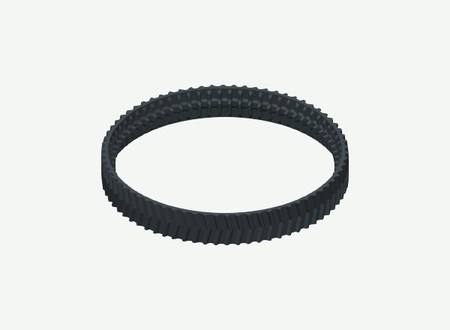
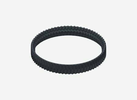
Track R78 70 Teeth (left + right) · TPU2
  1. Use the 70-tooth track print masters supplied in this package.
  2. Seat the central guides in the wheel grooves. Adjust both ends evenly and turn each track by hand.
12Fit the driver and controller
PrepareQty
Cytron MDD10A Rev2 dual motor driver1
Adafruit QT Py ESP32-S3, 54261
Adafruit Terminal Block BFF, 64951
Adafruit INA219 STEMMA QT, 9041
M3 × 6 socket-head screw4
M2 × 6 screw, non-countersunk6
M2 washer, 0.3 mm thick6
  1. Secure the MDD10A with four M3 × 6 screws.
  2. Use four M2 × 6 screws and 0.3 mm washers for the BFF, and two of each for the INA219.
13Fit the speaker and amplifier
PrepareQty
Speaker, 3 W, 4 ohm, 2-pin connector with 2 mm pitch1
MAX98357A amplifier module1
Splash-resistant acoustic membrane, fitted to the inner grille lip1
M3 × 6 socket-head screw2
M2 × 6 screw, non-countersunk2
M2 washer, 0.5 mm thick2
  1. Fix the speaker with two M3 × 6 screws above its grille.
  2. Seat the amplifier on its two mounting posts and two support pillars. Use two M2 × 6 screws with 0.5 mm washers.
14Fit the computer carrier and servo adapter
PrepareQty
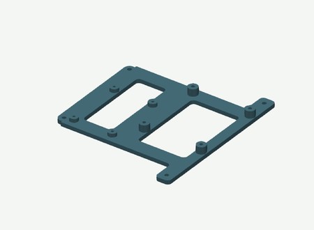
Pi Adapter · PETG1
Jetson Adapter · PETG1
Waveshare Bus Servo Adapter A1
Pi only: HAT mounting screws and spacers, supplied with the HAT1 kit
M3 × 6 socket-head screw2
M3 × 8 socket-head screw2
M3 washer, 0.5 mm thick4
M2.5 × 8 screw, non-countersunk4
M2.5 washer, 0.5 mm thick4
Jetson only: M3 × 8 socket-head screw, no washer2
  1. Choose one carrier: Jetson or Pi.
  2. Use the two M3 × 6 screws at the front and the two M3 × 8 screws at the rear, with one 0.5 mm washer each.
  3. For Jetson, secure the two retaining tabs with two M3 × 8 screws, without washers.
  4. For Pi/HAT, use the screws and spacers supplied with the HAT; prepare this assembly before fitting the carrier in the hull.
15Fit the camera option
PrepareQty
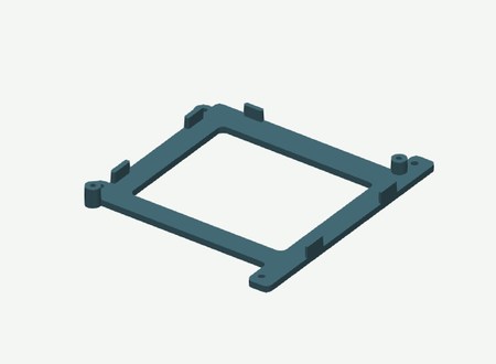
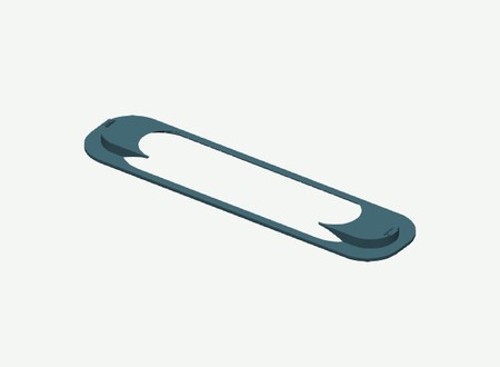
Gemini Window Adapter · PETG1
RealSense Insert · PETG1
Gemini Flush Insert · PETG1
RealSense D455 OR Orbbec Gemini 21
RealSense only: M4 × 10 socket-head screw2
Gemini only: M3 × 8 socket-head screw2
  1. For RealSense, slide the support insert down from the top, then use its two M4 × 10 screws.
  2. For Gemini, use the flush insert and the window bezel instead. Secure the camera with two M3 × 8 screws; keep the USB opening clear.
16Fit the LiDAR carriage
PrepareQty
Lidar dovetail carriage · PETG1
SLAMTEC RPLIDAR C11
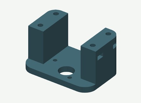
M3 × 10 socket-head screw2
M2.5 × 6 socket-head screw4
M3 × 20 socket-head screw1
  1. With the carriage removed, secure the LiDAR base to the hull with two M3 × 10 screws.
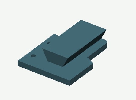
  2. Secure the C1 to the carriage with four M2.5 × 6 screws, slide it onto the base and lock it with the M3 × 20 screw, without a washer, into the M3 insert.
17Fit power distribution and cooling

Exploded assembly

PrepareQty
XT30 distribution base · PETG1
XT30 distribution lid · PETG1
XT30 insulating separator · PETG1
3010 fan, 12 V2
12-cell battery pack, 3S4P, with BMS, 110 × 67 × 35 mm1
Power harness wire, fuse, switches and USB cables1
DC male barrel plug, 5.5 × 2.5 mm, 9.5 mm barrel, centre positive — Jetson power1
DC male barrel plug matching the input of the Pi 5 V power supply1
DC male barrel plug, 5.5 × 2.1 mm — Waveshare Bus Servo Adapter A power1
DC male barrel plug, 5.5 × 2.1 mm — battery extension to the panel socket1
XT30 enclosure connectors: 1 input + 4 outputs, from the BOM connector pairs5
M2.5 × 10 low-head screw, head diameter 5 mm maximum4
  1. Clip the two fans into their mounts.
  2. Assemble the XT30 base, insulating separator and lid with four low-head M2.5 × 10 screws.
18Fit the arm plate and build the arm
PrepareQty
Arm Mounting Platform · PLA1
SO101 Base · PLA1
SO101 Shoulder rotation · PLA1
SO101 Base motor holder · PLA1
SO101 Shoulder bracket cable clip · PLA1
SO101 Upper arm cable clip · PLA1
SO101 Forearm cable clip · PLA1
SO101 Wrist cable clip · PLA1
SO101 Wrist bracket · PLA1
ST3215 12 V serial bus servo5
M3 × 10 socket-head screw4
M4 × 25 countersunk 90-degree screw4
M4 hex nut4
Kit screw: M2 × 6, original servo head20
Kit screw: M3 × 6, original servo head37
  1. Fit the arm plate with four M3 × 10 socket-head screws. Do not add washers in the counterbores.
  2. Use the original servo screw packs for the SO101 joints. Keep the camera and servo cables in the printed guides.
  3. For the wrist-camera cable, heat the printed clips to 70 °C, then close them around the cable.
19Build the gripper and wrist camera
PrepareQty
NC90 side shield (left + right) · PLA2
NC90 Pinion · PLA1
NC90 Cable guide · PLA1
NC90 jaw extended rack (left + right) · PLA2
Gripper Camera Mount · PLA1
NC90 Base extended rails · PLA1
CF35-12 gripper servo1
Wrist USB camera for the R30 mount, 21 × 13.5 mm PCB hole pattern1
Kit screw: M3 × 6 cross-head ISO704511
Kit screw: #1-42 x3/16 inch typeAB6
M2 × 6 screw, non-countersunk, for wrist camera PCB4
M3 × 10 socket-head screw, for wrist camera bracket2
M3 hex nut, for wrist camera bracket2
  1. Use the widened NC90 jaws and rails, keeping the two racks in phase.
  2. Fit the current camera mount. Retain the original gripper screw types.
  3. Fix the R30 camera bracket to the gripper with two M3 × 10 screws and two M3 nuts, without washers. Fix the matching camera PCB with four M2 × 6 screws.
20Close the hull and fit the bin
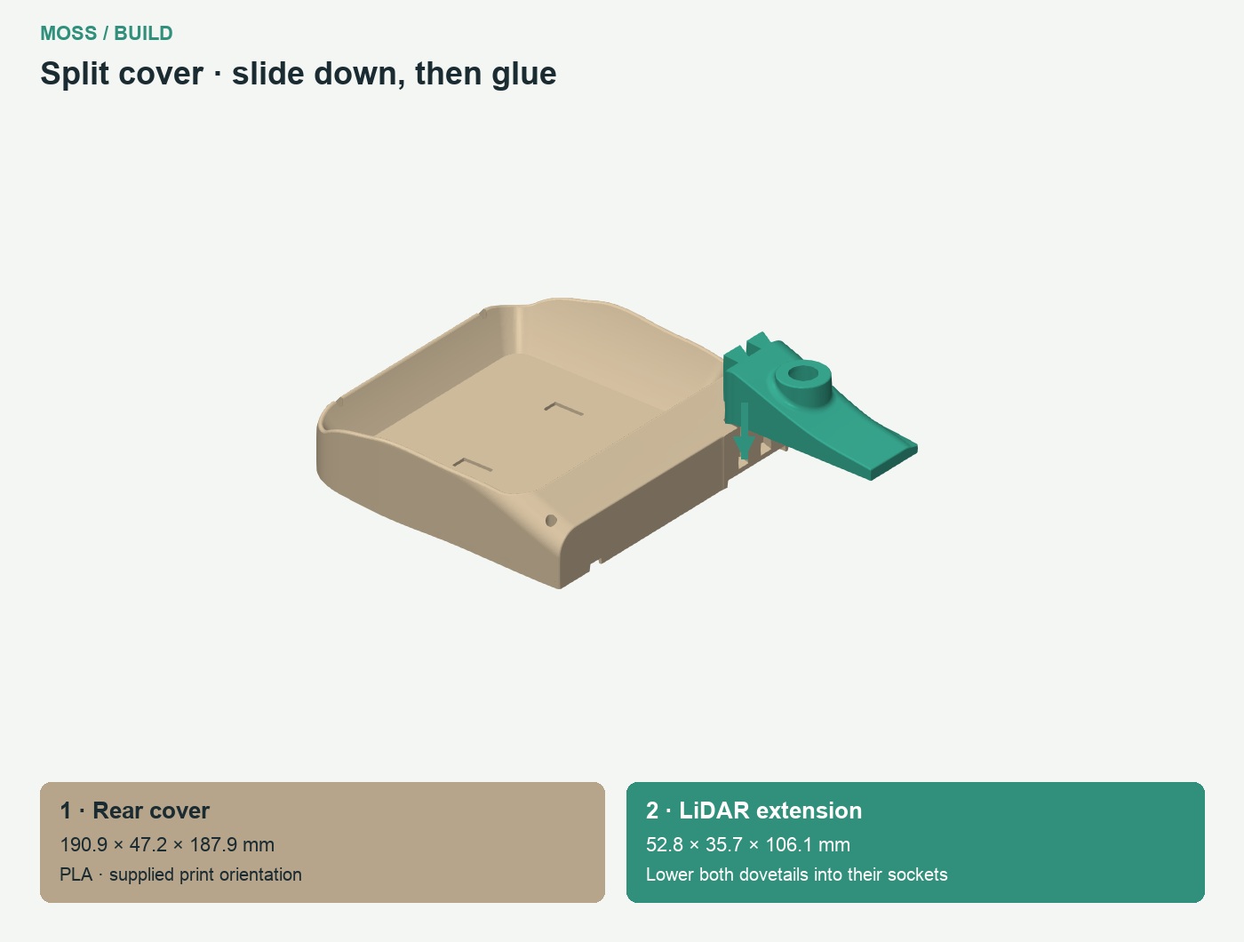
Two-piece upper cover: lower the LiDAR extension into the two dovetail sockets from above
PrepareQty
Motor access hatch 10 screws · PETG1
Upper cover · PLA1
Split cover · rear section · PLA1
Split cover · LiDAR extension · PLA1
Magnet, 20 x10 x2 mm4
Small two-part epoxy adhesive kit, two tubes (resin + hardener), for the magnets and split cover1 kit
M3 × 10 countersunk 90-degree screw, head diameter 6.4 mm maximum10
M3 × 10 countersunk 90-degree screw, head diameter 5.6 mm maximum4
  1. For the split cover: test-fit the two pieces off the rover. Lower the LiDAR extension from above into both dovetail sockets. Apply a thin layer of two-part epoxy on the mating faces, seat the joint, align the outer surfaces and hold until cured. The glued cover then mounts with the same four screws as the one-piece cover.
  2. Close the motor hatch with ten M3 × 10 countersunk screws.
  3. Fit the upper cover with four M3 × 10 countersunk screws.
  4. Check the polarity of all four magnets, then glue them into their pockets with epoxy. Let the epoxy cure before fitting the bin.

Your print set

Standard/default settings. 15% gyroid infill; for tracks, 15% standard-profile infill, not gyroid.

106 piecesGroup overview image

Each preview uses the supplied STL orientation. Choose a hull, cover, camera and computer option. Material is shown on every part. Two-piece hull · Two-piece cover · Outer-frame diagonal placement.

Hull options

One-piece hull in its print orientation

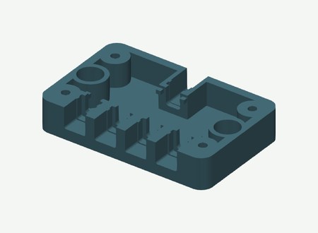
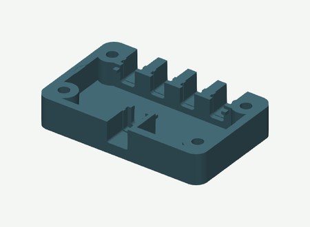
One-piece hull

PETG · Qty 1
Download STL
OrientationFlat exterior base down
Rear hull — motors and computer in its print orientation

Rear hull — motors and computer

PETG · Qty 1
Download STL
OrientationFlat exterior base down
Front hull — battery and camera in its print orientation

Front hull — battery and camera

PETG · Qty 1
Download STL
OrientationFlat exterior base down

Outer track frames

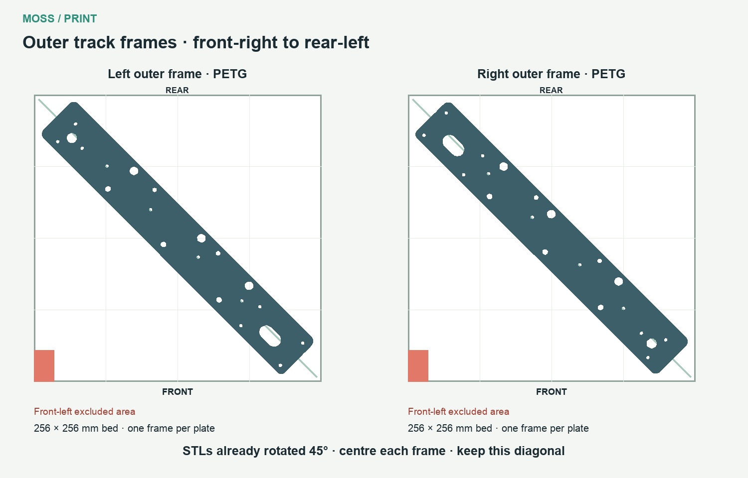
Print the outer frames separately on the front-right to rear-left diagonal. The STLs are already rotated. Placement guide.

Outer frames placed front-right to rear-left, clear of the front-left excluded zone
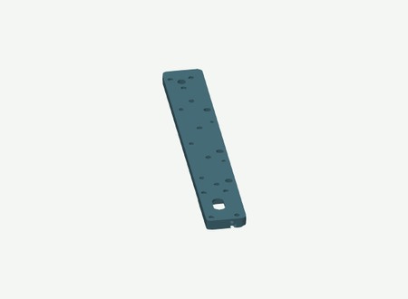
Left Outer Track Frame in its print orientation

Left Outer Track Frame

PETG · Qty 1
Download STL
OrientationFlat, 45 degrees: front-right to rear-left diagonal; centre on the plate. Supplied STL is already rotated. Print each outer frame separately.
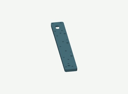
Right Outer Track Frame in its print orientation

Right Outer Track Frame

PETG · Qty 1
Download STL
OrientationFlat, 45 degrees: front-right to rear-left diagonal; centre on the plate. Supplied STL is already rotated. Print each outer frame separately.
Left inner tensioner cover in its print orientation

Left inner tensioner cover

PETG · Qty 1
Download STL
OrientationExisting print contact face retained
Right inner tensioner cover in its print orientation

Right inner tensioner cover

PETG · Qty 1
Download STL
OrientationExisting print contact face retained

Inner frames & spacers

Left inner track frame in its print orientation

Left inner track frame

PETG · Qty 1
Download STL
OrientationExisting print contact face retained
Right inner track frame in its print orientation

Right inner track frame

PETG · Qty 1
Download STL
OrientationExisting print contact face retained
SP12 · Left Spacer cross member -40 in its print orientation

SP12 · Left Spacer cross member -40

PETG · Qty 1
Download STL
OrientationExisting print contact face retained
SP12 · Left Spacer cross member 40 in its print orientation

SP12 · Left Spacer cross member 40

PETG · Qty 1
Download STL
OrientationExisting print contact face retained
SP12 · Right Spacer cross member -40 in its print orientation

SP12 · Right Spacer cross member -40

PETG · Qty 1
Download STL
OrientationExisting print contact face retained
SP12 · Right Spacer cross member 40 in its print orientation

SP12 · Right Spacer cross member 40

PETG · Qty 1
Download STL
OrientationExisting print contact face retained
SP01 · Left Spacer road wheel -70 inner ID01 in its print orientation

SP01 · Left Spacer road wheel -70 inner ID01

PETG · Qty 1
Download STL
OrientationExisting print contact face retained
SP01 · Left Spacer road wheel 0 inner ID01 in its print orientation

SP01 · Left Spacer road wheel 0 inner ID01

PETG · Qty 1
Download STL
OrientationExisting print contact face retained
SP01 · Left Spacer road wheel 70 inner ID01 in its print orientation

SP01 · Left Spacer road wheel 70 inner ID01

PETG · Qty 1
Download STL
OrientationExisting print contact face retained
SP01 · Right Spacer road wheel -70 inner ID01 in its print orientation

SP01 · Right Spacer road wheel -70 inner ID01

PETG · Qty 1
Download STL
OrientationExisting print contact face retained
SP01 · Right Spacer road wheel 0 inner ID01 in its print orientation

SP01 · Right Spacer road wheel 0 inner ID01

PETG · Qty 1
Download STL
OrientationExisting print contact face retained
SP01 · Right Spacer road wheel 70 inner ID01 in its print orientation

SP01 · Right Spacer road wheel 70 inner ID01

PETG · Qty 1
Download STL
OrientationExisting print contact face retained
SP05 · Left Spacer tensioner inner ID05 in its print orientation

SP05 · Left Spacer tensioner inner ID05

PETG · Qty 1
Download STL
OrientationExisting print contact face retained
SP05 · Right Spacer tensioner inner ID05 in its print orientation

SP05 · Right Spacer tensioner inner ID05

PETG · Qty 1
Download STL
OrientationExisting print contact face retained
SP03 · Left Spacer drive inner ID03 in its print orientation

SP03 · Left Spacer drive inner ID03

PETG · Qty 1
Download STL
OrientationExisting print contact face retained
SP03 · Right Spacer drive inner ID03 in its print orientation

SP03 · Right Spacer drive inner ID03

PETG · Qty 1
Download STL
OrientationExisting print contact face retained

Motor bay & LiDAR mounts

Motor access hatch 10 screws in its print orientation

Motor access hatch 10 screws

PETG · Qty 1
Download STL
OrientationExisting print contact face retained
Motor Mount Left in its print orientation

Motor Mount Left

PETG · Qty 1
Download STL
OrientationBroad motor-facing flat face down
Motor Mount Right in its print orientation

Motor Mount Right

PETG · Qty 1
Download STL
OrientationBroad motor-facing flat face down
Left bearing retainer in its print orientation

Left bearing retainer

PETG · Qty 1
Download STL
OrientationExisting print contact face retained
Right bearing retainer in its print orientation

Right bearing retainer

PETG · Qty 1
Download STL
OrientationExisting print contact face retained
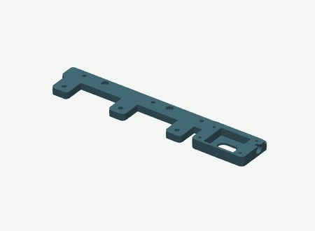
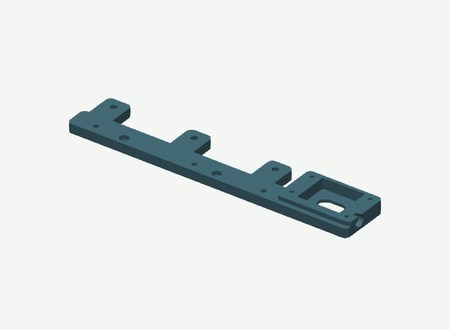
Lidar Base in its print orientation

Lidar Base

PETG · Qty 1
Download STL
OrientationFlat base down
Lidar dovetail carriage in its print orientation

Lidar dovetail carriage

PETG · Qty 1
Download STL
OrientationExisting print contact face retained

Outer spacers & covers

SP02 · Left Spacer road wheel -70 outer ID02 in its print orientation

SP02 · Left Spacer road wheel -70 outer ID02

PETG · Qty 1
Download STL
OrientationExisting print contact face retained
SP02 · Left Spacer road wheel 0 outer ID02 in its print orientation

SP02 · Left Spacer road wheel 0 outer ID02

PETG · Qty 1
Download STL
OrientationExisting print contact face retained
SP02 · Left Spacer road wheel 70 outer ID02 in its print orientation

SP02 · Left Spacer road wheel 70 outer ID02

PETG · Qty 1
Download STL
OrientationExisting print contact face retained
SP02 · Right Spacer road wheel -70 outer ID02 in its print orientation

SP02 · Right Spacer road wheel -70 outer ID02

PETG · Qty 1
Download STL
OrientationExisting print contact face retained
SP02 · Right Spacer road wheel 0 outer ID02 in its print orientation

SP02 · Right Spacer road wheel 0 outer ID02

PETG · Qty 1
Download STL
OrientationExisting print contact face retained
SP02 · Right Spacer road wheel 70 outer ID02 in its print orientation

SP02 · Right Spacer road wheel 70 outer ID02

PETG · Qty 1
Download STL
OrientationExisting print contact face retained
SP06 · Left Spacer tensioner outer ID06 in its print orientation

SP06 · Left Spacer tensioner outer ID06

PETG · Qty 1
Download STL
OrientationExisting print contact face retained
SP06 · Right Spacer tensioner outer ID06 in its print orientation

SP06 · Right Spacer tensioner outer ID06

PETG · Qty 1
Download STL
OrientationExisting print contact face retained
SP04 · Left Spacer drive outer HEX12 L12.6 ID04 in its print orientation

SP04 · Left Spacer drive outer HEX12 L12.6 ID04

PETG · Qty 1
Download STL
OrientationExisting print contact face retained
SP04 · Right Spacer drive outer HEX12 L12.6 ID04 in its print orientation

SP04 · Right Spacer drive outer HEX12 L12.6 ID04

PETG · Qty 1
Download STL
OrientationExisting print contact face retained
Left Cover tensioner outer in its print orientation

Left Cover tensioner outer

PETG · Qty 1
Download STL
OrientationExisting print contact face retained
Right Cover tensioner outer in its print orientation

Right Cover tensioner outer

PETG · Qty 1
Download STL
OrientationExisting print contact face retained

Drive & idler wheels

Left 22T idler wheel inner half in its print orientation

Left 22T idler wheel inner half

PETG · Qty 1
Download STL
OrientationExisting print contact face retained
Left 22T idler wheel outer half in its print orientation

Left 22T idler wheel outer half

PETG · Qty 1
Download STL
OrientationExisting print contact face retained
Right 22T idler wheel inner half in its print orientation

Right 22T idler wheel inner half

PETG · Qty 1
Download STL
OrientationExisting print contact face retained
Right 22T idler wheel outer half in its print orientation

Right 22T idler wheel outer half

PETG · Qty 1
Download STL
OrientationExisting print contact face retained
Left HEX12 drive wheel inner half in its print orientation

Left HEX12 drive wheel inner half

PETG · Qty 1
Download STL
OrientationExisting print contact face retained
Left HEX12 drive wheel outer half in its print orientation

Left HEX12 drive wheel outer half

PETG · Qty 1
Download STL
OrientationExisting print contact face retained
Right HEX12 drive wheel inner half in its print orientation

Right HEX12 drive wheel inner half

PETG · Qty 1
Download STL
OrientationExisting print contact face retained
Right HEX12 drive wheel outer half in its print orientation

Right HEX12 drive wheel outer half

PETG · Qty 1
Download STL
OrientationExisting print contact face retained

Road wheels

Left 625 road wheel -70 inner half in its print orientation

Left 625 road wheel -70 inner half

PETG · Qty 1
Download STL
OrientationExisting print contact face retained
Left 625 road wheel -70 outer half in its print orientation

Left 625 road wheel -70 outer half

PETG · Qty 1
Download STL
OrientationExisting print contact face retained
Left 625 road wheel 70 inner half in its print orientation

Left 625 road wheel 70 inner half

PETG · Qty 1
Download STL
OrientationExisting print contact face retained
Left 625 road wheel 70 outer half in its print orientation

Left 625 road wheel 70 outer half

PETG · Qty 1
Download STL
OrientationExisting print contact face retained
Right 625 road wheel -70 inner half in its print orientation

Right 625 road wheel -70 inner half

PETG · Qty 1
Download STL
OrientationExisting print contact face retained
Right 625 road wheel -70 outer half in its print orientation

Right 625 road wheel -70 outer half

PETG · Qty 1
Download STL
OrientationExisting print contact face retained
Right 625 road wheel 70 inner half in its print orientation

Right 625 road wheel 70 inner half

PETG · Qty 1
Download STL
OrientationExisting print contact face retained
Right 625 road wheel 70 outer half in its print orientation

Right 625 road wheel 70 outer half

PETG · Qty 1
Download STL
OrientationExisting print contact face retained
Left 625 road wheel 0 inner half in its print orientation

Left 625 road wheel 0 inner half

PETG · Qty 1
Download STL
OrientationExisting print contact face retained
Left 625 road wheel 0 outer half in its print orientation

Left 625 road wheel 0 outer half

PETG · Qty 1
Download STL
OrientationExisting print contact face retained
Right 625 road wheel 0 inner half in its print orientation

Right 625 road wheel 0 inner half

PETG · Qty 1
Download STL
OrientationExisting print contact face retained
Right 625 road wheel 0 outer half in its print orientation

Right 625 road wheel 0 outer half

PETG · Qty 1
Download STL
OrientationExisting print contact face retained

Power distribution housing

XT30 distribution base in its print orientation

XT30 distribution base

PETG · Qty 1
Download STL
OrientationExisting print contact face retained
XT30 distribution lid in its print orientation

XT30 distribution lid

PETG · Qty 1
Download STL
OrientationExisting print contact face retained
XT30 insulating separator in its print orientation

XT30 insulating separator

PETG · Qty 1
Download STL
OrientationExisting print contact face retained

Slides, retainers & spacers

Left Slider outer in its print orientation

Left Slider outer

PETG · Qty 1
Download STL
OrientationExisting print contact face retained
Left Cover motor bearing in its print orientation

Left Cover motor bearing

PETG · Qty 1
Download STL
OrientationExisting print contact face retained
Right Slider outer in its print orientation

Right Slider outer

PETG · Qty 1
Download STL
OrientationExisting print contact face retained
Right Cover motor bearing in its print orientation

Right Cover motor bearing

PETG · Qty 1
Download STL
OrientationExisting print contact face retained
Left inner tensioner slider in its print orientation

Left inner tensioner slider

PETG · Qty 1
Download STL
OrientationExisting print contact face retained
Right inner tensioner slider in its print orientation

Right inner tensioner slider

PETG · Qty 1
Download STL
OrientationExisting print contact face retained
SP07 · Left Spacer tensioner retainer inner ID07 in its print orientation

SP07 · Left Spacer tensioner retainer inner ID07

PETG · Qty 1
Download STL
OrientationExisting print contact face retained
SP08 · Left Spacer tensioner retainer outer ID08 in its print orientation

SP08 · Left Spacer tensioner retainer outer ID08

PETG · Qty 1
Download STL
OrientationExisting print contact face retained
SP10 · Left Spacer tensioner center in its print orientation

SP10 · Left Spacer tensioner center

PETG · Qty 1
Download STL
OrientationExisting print contact face retained
SP07 · Right Spacer tensioner retainer inner ID07 in its print orientation

SP07 · Right Spacer tensioner retainer inner ID07

PETG · Qty 1
Download STL
OrientationExisting print contact face retained
SP08 · Right Spacer tensioner retainer outer ID08 in its print orientation

SP08 · Right Spacer tensioner retainer outer ID08

PETG · Qty 1
Download STL
OrientationExisting print contact face retained
SP10 · Right Spacer tensioner center in its print orientation

SP10 · Right Spacer tensioner center

PETG · Qty 1
Download STL
OrientationExisting print contact face retained
SP09 · Left Spacer road wheel -70 center in its print orientation

SP09 · Left Spacer road wheel -70 center

PETG · Qty 1
Download STL
OrientationExisting print contact face retained
SP09 · Left Spacer road wheel 0 center in its print orientation

SP09 · Left Spacer road wheel 0 center

PETG · Qty 1
Download STL
OrientationExisting print contact face retained
SP09 · Left Spacer road wheel 70 center in its print orientation

SP09 · Left Spacer road wheel 70 center

PETG · Qty 1
Download STL
OrientationExisting print contact face retained
SP09 · Right Spacer road wheel -70 center in its print orientation

SP09 · Right Spacer road wheel -70 center

PETG · Qty 1
Download STL
OrientationExisting print contact face retained
SP09 · Right Spacer road wheel 0 center in its print orientation

SP09 · Right Spacer road wheel 0 center

PETG · Qty 1
Download STL
OrientationExisting print contact face retained
SP09 · Right Spacer road wheel 70 center in its print orientation

SP09 · Right Spacer road wheel 70 center

PETG · Qty 1
Download STL
OrientationExisting print contact face retained
SP11 · Left Drive bearing to collar spacer in its print orientation

SP11 · Left Drive bearing to collar spacer

PETG · Qty 1
Download STL
OrientationExisting print contact face retained
SP11 · Right Drive bearing to collar spacer in its print orientation

SP11 · Right Drive bearing to collar spacer

PETG · Qty 1
Download STL
OrientationExisting print contact face retained

Upper cover

One-piece upper cover in its print orientation

One-piece upper cover

PLA · Qty 1
Download STL
OrientationRear edge down
Split cover · rear section in its print orientation

Split cover · rear section

PLA · Qty 1
Download STL
OrientationRear edge down; supplied STL orientation
Split cover · LiDAR extension in its print orientation

Split cover · LiDAR extension

PLA · Qty 1
Download STL
OrientationFront edge down; supplied STL orientation

Bin

Bin 20x10x2 magnet pockets in its print orientation

Bin 20x10x2 magnet pockets

PLA · Qty 1
Download STL
OrientationExisting print contact face retained

Arm plate

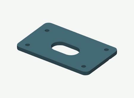
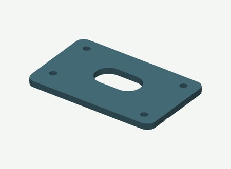
Arm Mounting Platform in its print orientation

Arm Mounting Platform

PLA · Qty 1
Download STL
OrientationFlat underside down

Arm base & shoulder

SO101 Base in its print orientation

SO101 Base

PLA · Qty 1
Download STL
OrientationExisting print contact face retained
SO101 Shoulder rotation in its print orientation

SO101 Shoulder rotation

PLA · Qty 1
Download STL
OrientationExisting print contact face retained
SO101 Base motor holder in its print orientation

SO101 Base motor holder

PLA · Qty 1
Download STL
OrientationExisting print contact face retained
SO101 Shoulder bracket cable clip in its print orientation

SO101 Shoulder bracket cable clip

PLA · Qty 1
Download STL
OrientationExisting print contact face retained

Arm links

SO101 Upper arm cable clip in its print orientation

SO101 Upper arm cable clip

PLA · Qty 1
Download STL
OrientationExisting print contact face retained
SO101 Forearm cable clip in its print orientation

SO101 Forearm cable clip

PLA · Qty 1
Download STL
OrientationExisting print contact face retained
SO101 Wrist cable clip in its print orientation

SO101 Wrist cable clip

PLA · Qty 1
Download STL
OrientationExisting print contact face retained
SO101 Wrist bracket in its print orientation

SO101 Wrist bracket

PLA · Qty 1
Download STL
OrientationExisting print contact face retained

Gripper & wrist camera

NC90 Right side shield in its print orientation

NC90 Right side shield

PLA · Qty 1
Download STL
OrientationExisting print contact face retained
NC90 Pinion in its print orientation

NC90 Pinion

PLA · Qty 1
Download STL
OrientationExisting print contact face retained
NC90 Cable guide in its print orientation

NC90 Cable guide

PLA · Qty 1
Download STL
OrientationExisting print contact face retained
NC90 Right jaw extended rack in its print orientation

NC90 Right jaw extended rack

PLA · Qty 1
Download STL
OrientationExisting print contact face retained
Gripper Camera Mount in its print orientation

Gripper Camera Mount

PLA · Qty 1
Download STL
OrientationSupplied print orientation for current IMX335 B mount
NC90 Left side shield in its print orientation

NC90 Left side shield

PLA · Qty 1
Download STL
OrientationExisting print contact face retained
NC90 Base extended rails in its print orientation

NC90 Base extended rails

PLA · Qty 1
Download STL
OrientationExisting print contact face retained
NC90 Left jaw extended rack in its print orientation

NC90 Left jaw extended rack

PLA · Qty 1
Download STL
OrientationExisting print contact face retained

Left track

Left Track R78 70 Teeth in its print orientation

Left Track R78 70 Teeth

TPU · Qty 1
Download STL
OrientationFlat side down; 70 teeth, 6.8 mm central guides

Right track

Right Track R78 70 Teeth in its print orientation

Right Track R78 70 Teeth

TPU · Qty 1
Download STL
OrientationFlat side down; same printable part as left

Jetson carrier

Jetson Adapter in its print orientation

Jetson Adapter

PETG · Qty 1
Download STL
OrientationFlat underside down

Pi carrier

Pi Adapter in its print orientation

Pi Adapter

PETG · Qty 1
Download STL
OrientationFlat underside down

Gemini inserts

Gemini Window Adapter in its print orientation

Gemini Window Adapter

PETG · Qty 1
Download STL
OrientationFlat front frame down; curved ends retained
Gemini Flush Insert in its print orientation

Gemini Flush Insert

PETG · Qty 1
Download STL
OrientationRear flat face down; plain top-entry key

RealSense insert

RealSense Insert in its print orientation

RealSense Insert

PETG · Qty 1
Download STL
OrientationRear flat face down; top-entry screw-support key

What to buy

Parts and hardware for one rover using separate modules. Choose one computer and one camera option.

Open the bill of materials

One rover, using separate off-the-shelf modules. Choose one computer and one depth camera.

Control and audio

ItemQuantityNote
Adafruit QT Py ESP32-S3, 8 MB flash, no PSRAM, ref.54261
Adafruit Terminal Block BFF, ref.64951
Adafruit INA219 STEMMA QT, ref.9041
STEMMA QT cable, 300 mm, ref.53841
Cytron MDD10A Rev2 dual motor driver1
Waveshare Bus Servo Adapter A1
MAX98357A amplifier module1
Speaker, 3 W, 4 ohm1
Acoustic splash membrane and compatible adhesive1EPTFE or non woven fabric membrane.

Drive

ItemQuantityNote
JGB37-520, 12 V, 90:1, 110 rpm, Hall encoder, 6 mm D-shaft2
625 bearing12
608 bearing4
626 bearing4
LK05 — shaft collar, 5 mm bore, Ø10 × 5 mm12
LK06 — shaft collar, 6 mm bore, Ø11 × 5 mm2
LK08 — shaft collar, 8 mm bore, Ø16 × 8 mm4
Smooth steel axle, 5 ×70 mm finished length6Check the physical stack before cutting stock.
Smooth steel axle, 6 ×77 mm finished length2
Smooth steel axle, 8 ×87 mm finished length2
Rigid motor-to-shaft coupling, 6 mm bores2
HEX12 metal wheel hub, 6 mm bore, 18 mm length2

LK05/LK06/LK08 are guide identifiers for purchased shaft collars, also called lock rings. All spacer and collar references.

Arm, gripper and body

ItemQuantityNote
ST3215 12 V serial bus servo5Keep the original servo screw packs.
CF35-12 constant-force gripper servo1
3010 fan, 12 V2
Magnet, 20 ×10 ×2 mm4Glue into the pockets with epoxy; check polarity before gluing.
Small two-part epoxy adhesive kit, two tubes (resin + hardener)1 kitFor gluing the four bin magnets and joining the two-piece hull and cover when printing on a smaller printer.
M3 brass heat-set insert, OD4 mm, length 6 mm1110 in the hull and 1 in the LiDAR base.

Power and wiring — module-based rover

ItemQuantityNote
12-cell battery pack, 3S4P, with BMS1110 × 67 × 35 mm.
12.6 V CC/CV charger for the selected 3S pack1
Emergency stop LA16-11ZS/A, 16 mm1
KCD11 two-pin rocker switch and splash cover1
Inline blade-fuse holder, 14 AWG1
ATC blade fuse, 15 A1
Amass XT30 male/female connector pair6
DC panel socket, 5.5 ×2.1 mm2Female panel-mount sockets.
DC male barrel plug — computer power branch1Jetson: 5.5 × 2.5 mm, 9.5 mm barrel, centre positive (NVIDIA specification). Pi option: choose the plug that matches the input of the selected 5 V power supply. These are alternatives.
DC male barrel plug, 5.5 × 2.1 mm — servo power branch1For the Waveshare Bus Servo Adapter A (Waveshare specification).
DC male barrel plug, 5.5 × 2.1 mm — battery extension1Matches the 5.5 × 2.1 mm panel socket listed above.
Wire, ferrules and heat-shrink1 lot
Plugable USB hub, model USB2-2port1
USB-C to USB-A cable, 30 cm3
RealSense camera cable1Lazada product link · RealSense option only.

Choose one computer

ItemQuantityNote
NVIDIA Jetson Orin Nano Super Developer Kit1Use the Jetson carrier.
OR Raspberry Pi5 with its cooler, storage and appropriate 5 V supply1Use the Pi carrier and the mounting screws and spacers supplied with the HAT.

Sensors

ItemQuantityNote
Intel RealSense D455 OR Orbbec Gemini 21Use the matching printed insert(s); these are alternatives.
SLAMTEC RPLIDAR C11
Wrist USB camera for the R30 mount1PCB mounting-hole pattern: 21 × 13.5 mm.

Fasteners by assembly

Quantities are for one rover. Use the assembly step to locate each fastener.

AssemblyFasteners for one rover
Choose the hull and fit the inserts11 × M3 heat-set insert, OD4 mm, length 6 mm; 6 × Split hull only: M4 × 15 socket-head screw; 6 × Split hull only: M4 hex nut, 7 mm across flats; 6 × Split hull only: M4 washer, Ø9 × 0.8 mm
Build the six road wheels18 × M3 × 35 socket-head screw; 18 × M3 hex nut
Build the two drive wheels6 × M3 × 20 socket-head screw; 6 × M3 hex nut
Build the two idler wheels6 × M3 × 25 socket-head screw; 6 × M3 hex nut
Fit the motors and inner bearing retainers8 × M4 × 20 socket-head screw; 8 × M4 hex nut; 12 × M3 × 8 socket-head screw
Fit the inner track frames6 × M4 × 15 socket-head screw; 6 × M4 hex nut
Fit the drive axles and outer bearing covers6 × M3 × 15 socket-head screw; 6 × M3 hex nut
Fit the idler slides and tensioners16 × M3 × 15 socket-head screw; 16 × M3 hex nut; 4 × M4 × 35 socket-head screw; 8 × M4 hex nut; 4 × M4 washer
Close the track frames4 × M4 × 60 socket-head screw; 4 × M4 hex nut; 4 × M4 washer
Fit the driver and controller4 × M3 × 6 socket-head screw; 6 × M2 × 6 screw, non-countersunk; 6 × M2 washer, 0.3 mm thick
Fit the speaker and amplifier2 × M3 × 6 socket-head screw; 2 × M2 × 6 screw, non-countersunk; 2 × M2 washer, 0.5 mm thick
Fit the computer carrier and servo adapter2 × M3 × 6 socket-head screw; 2 × M3 × 8 socket-head screw; 4 × M3 washer, 0.5 mm thick; 4 × M2.5 × 8 screw, non-countersunk; 4 × M2.5 washer, 0.5 mm thick; 2 × Jetson only: M3 × 8 socket-head screw, no washer
Fit the camera option2 × RealSense only: M4 × 10 socket-head screw; 2 × Gemini only: M3 × 8 socket-head screw
Fit the LiDAR carriage2 × M3 × 10 socket-head screw; 4 × M2.5 × 6 socket-head screw; 1 × M3 × 20 socket-head screw
Fit power distribution and cooling4 × M2.5 × 10 low-head screw, head diameter 5 mm maximum
Fit the arm plate and build the arm4 × M3 × 10 socket-head screw; 4 × M4 × 25 countersunk 90-degree screw; 4 × M4 hex nut; 20 × Kit screw: M2 × 6, original servo head; 37 × Kit screw: M3 × 6, original servo head
Build the gripper and wrist camera11 × Kit screw: M3 × 6 cross-head ISO7045; 6 × Kit screw: #1-42 x3/16 inch typeAB; 4 × M2 × 6 screw, non-countersunk, for wrist camera PCB; 2 × M3 × 10 socket-head screw, for wrist camera bracket; 2 × M3 hex nut, for wrist camera bracket
Close the hull and fit the bin10 × M3 × 10 countersunk 90-degree screw, head diameter 6.4 mm maximum; 4 × M3 × 10 countersunk 90-degree screw, head diameter 5.6 mm maximum

Screw lengths are measured under the head, except countersunk screws, which use their full length. Retain the original heads supplied with the servo and gripper kits. Camera screw sets are alternatives.

Measured fastener lengths. Pi/HAT mounting hardware is supplied with the HAT; no separate screw purchase is added.

The supplied computer carriers are for the NVIDIA Jetson Orin Nano and Raspberry Pi 5. Choose one carrier and one camera option.

See the assembly cards.

Adhesive for the split hull and cover

Use the same two-part epoxy kit listed above. Retain the six M4 hull fixings and the four cover mounting screws.

Download BOM

Current files

The main Fusion and STEP files cover the one-piece set. The two-piece hull and upper cover have their own native Fusion assemblies. Arm meshes and track masters are also supplied as STL.

113 part STL files cover the alternatives, plus two optional fit coupons. The selected catalogue uses 106–109 pieces. Original project and upstream licence notices are included.